

Analysis of Brake Drum Cracking Causes
Automobile brake drum is an important functional part of the car, and it is also the most important component to measure the safety performance of the car. It is also the first component to be inspected in daily maintenance. Relevant data show that there are five main forms of brake drum failure: tortoise Cracks, cracks, bottom drop, excessive wear, abnormal wear. The following mainly discusses one of the main reasons for the first two types of fracture -thermal fatigue fracture caused by high temperature chilling.
Sampling plan and inspection basis
1. Sampling scheme
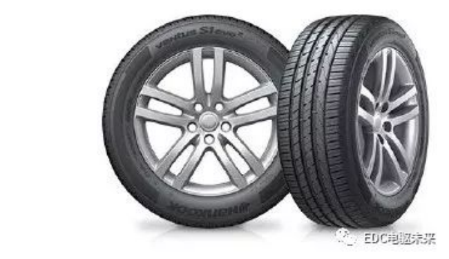
The source of samples for brake drum products this time is the scrapped products replaced by auto repair shops. 30 samples were purchased from six repair shops in Shijiazhuang, Gaocheng and Zhengding. Relatively large, there are many types of vehicles involved and many product models, and the service objects of these repair shops are also all over the country, so the samples purchased this time have a certain representativeness as shown in Figure 1.
The samples taken this time have different damage locations and degrees of damage, so that analysts can more comprehensively grasp the quality risk points of the sample.
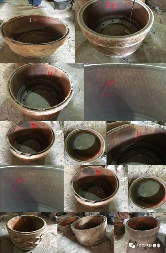
Figure 1
From the analysis of the appearance of the samples, the damage position of most of the samples is the cracks on the friction surface, and the reason for the cracks in the brake drum is that the brake drum will generate high temperature when the vehicle goes downhill for a long time. The brake drum shrinks sharply when it encounters water, so the friction surface of the brake drum produces cracks along the axis direction. The cracks extend as the braking continues, and finally the brake drum ruptures. Some brake drums found that their friction surface showed a piece of bright sparkle during the warranty period, which was caused by the brake drum encountering water at high temperature.
2. Test basis
This analysis is mainly based on GB/T 7216-2009 "Gray Iron Metallography", GB/T13298-2015 "Metallic Microstructure Inspection Method", GB/T9439-2010 "Gray Iron Castings", JB/T7711-2007 "Heat treatment of gray iron castings" and other standards.
The cause and confirmation of the cracking and cracking of the brake drum
By selecting 5 brake drums with cracks and cracking characteristics from the 30 brake drums found by the auto repair shop as samples, and sampling the dense cracks for experimental observation. The sampling method is: cut a piece of steel ingot with a square of 2cm on the working surface where the drum wall and the brake lining are in contact with dense cracks (no high temperature is generated during cutting to prevent phase transformation), mark the inner and outer walls of the steel ingot and number the corresponding sample. . After the sample is prepared, it is metallographically polished and etched (5% nitric acid alcohol solution is corroded at room temperature for 15 seconds) to obtain the following structure.
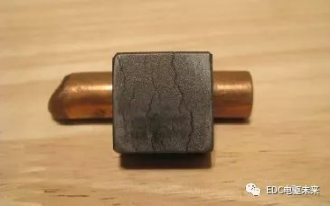
Figure 2.1 The surface of the failed brake drum after metallographic drum corrosion
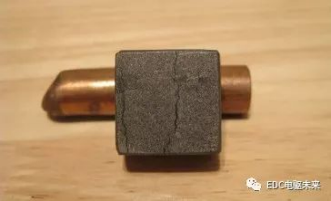
Figure 2.2 The surface of the failed brake drum after metallographic drum corrosion
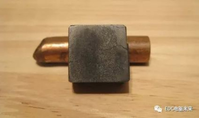
Figure 2.3 The surface of the failed brake drum after metallographic drum corrosion
Preliminary observation of the surface of the corroded samples is not difficult to find that each sample has one or two darker plaques, and the plaques are often perpendicular to the direction of crack extension and parallel to the direction of braking friction, and are often located in the middle of the crack. From this, it is not difficult to guess that the dark patches are the phase change structure formed by the local high temperature rapid cooling caused by the uneven heat generation of the brake drum during operation, and the cracks are first generated from the center of the phase change and perpendicular to the direction of the braking friction force. It extends on both sides and ends at the untransformed tissue. In order to prove the above conjecture, the author of this paper observed the five corroded samples under a 400x metallographic microscope and took the metallographic photos as follows:
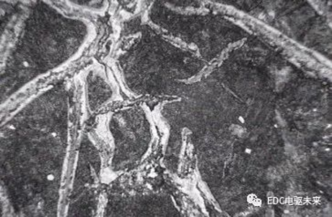
Fig. 2.4 Metallographic structure at the dark plaque of test block No. 1 (400×)
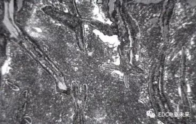
Fig. 2.5 Metallographic structure at the dark plaque of test block No. 2 (400×)
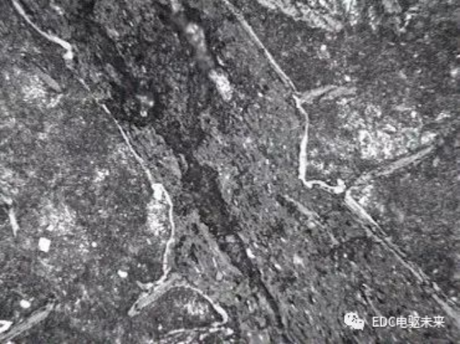
Fig. 2.6 Metallographic structure at the dark plaque of test block No. 3 (400×)
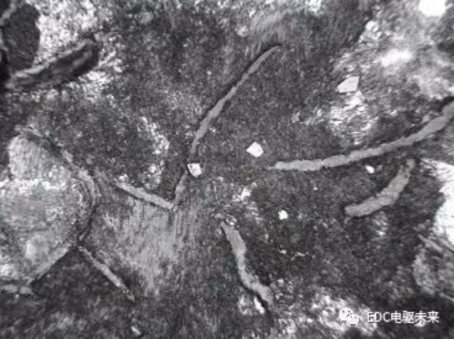
Fig. 2.7 Metallographic structure at the dark plaque of test block No. 4 (400×)
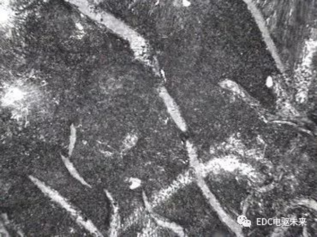
Fig. 2.8 Metallographic structure at the dark plaque of test block No. 5 (400×)
It is not difficult to find through these pictures: the local dark parts of the five test blocks have undergone high temperature (above 727 ℃) and undergone quenching transformation, and finally tempered sorbite or tempered trotter is formed. Because the structure is too fine, it is difficult to distinguish the boundary between ferrite and cementite under the light microscope, so only dark structure can be observed. Subsequently, the author of this paper made a 100-fold microscopic observation of the crack and took pictures. Several typical pictures were selected and listed as follows.
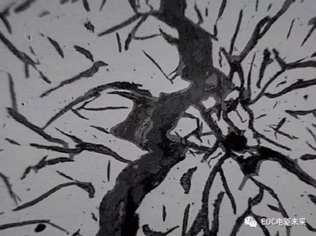
Fig. 2.9 Metallographic structure at the crack of No. 1 test block (100× not corroded)
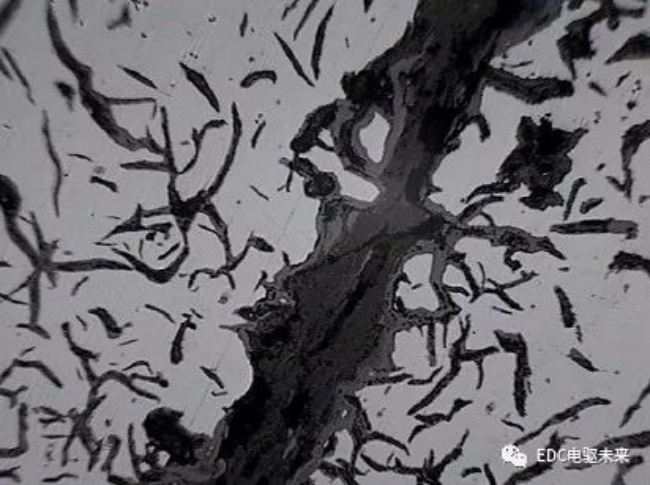
Figure 2.10 Metallographic structure at the crack of No. 2 test block (100× not corroded)
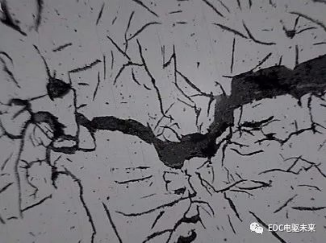
Figure 2.11 Metallographic structure at the crack of No. 3 test block (100× not corroded)
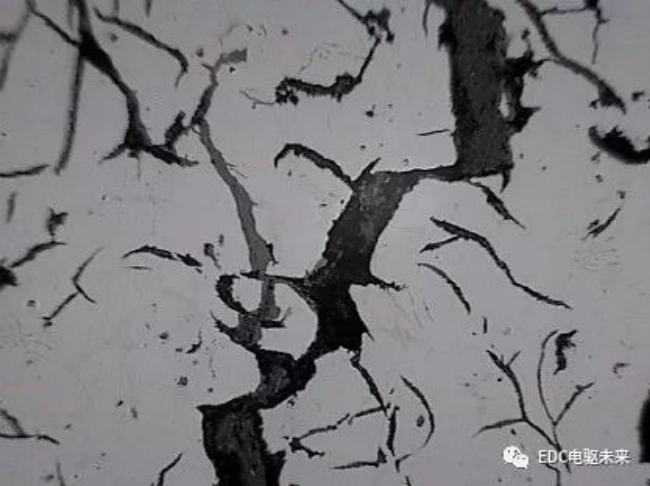
Figure 2.12 Metallographic structure at the crack of No. 4 test block (100× not corroded)
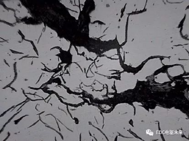
Figure 2.13 Metallographic structure at the crack of No. 5 test block (100× not corroded)
After observing the cracks of the five samples, it can be found that the entire crack extension direction is relatively straight, and the cracks extend along the graphite direction and connect from one graphite tip to another graphite tip almost invariably in a dendritic shape. Obvious brittle fracture characteristics, but when the crack extends to the untransformed region, the overall direction of the crack becomes curved, and finally ends at a graphite edge at a large angle to the overall direction of the crack. Based on this, it can be speculated that the part of the failed brake drum is cooled rapidly when it reaches a temperature higher than the phase transition temperature, so that the matrix of this part becomes a hardened structure. The structure is brittle and contains a large amount of residual phase transformation stress. When subjected to frequent compound stress (normal compressive stress and tangential friction stress generated by braking action and thermal stress generated by braking heat generation) for a period of time, Some stress concentrations in this part (the sharp corners of carbide or the tip of graphite, etc.) are subjected to combined stress greater than the fracture strength of the particle material, and initial cracks are initiated. As the crack extends to the untransformed matrix structure with a certain degree of plasticity, the matrix can relax a part of the stress through plastic deformation, and the tip of the crack is deformed and strengthened due to plastic deformation, so the extension path of the crack becomes tortuous, while the degree of stress concentration gradually decreases with the bending of the path, and finally the crack disappears into the matrix. To further verify this inference, we also did the following thermal fatigue tests simulating its working conditions.
High temperature chilling thermal fatigue test of brake drum
1. Sample preparation
A square ingot with a length and width of 1.5cm and a wall thickness of 1.5cm is cut out from the flange bottom of the failed brake drum, which is not affected by the high temperature phase change, and the residual stress affected layer on the cut surface is ground off. (Be careful not to generate new residual stress during grinding), and finally treat all the surface roughness of the ingot to ≤3.2μm.
2. Test operation
Heat the specimen to 880°C for one minute, take it out and put it in 20°C water to cool, and repeat this operation until cracks are observed with the naked eye, then blow dry for metallographic observation.
3, the test results
After the test, 30 test blocks were placed in the order of 37, 28, 30, 33, 36, 27, 30, 32, 40, 29, 30 times of high-temperature chilling, there are visible cracks. And the crack shape is consistent with the failure part of the brake drum.
4. Conclusion
The thermal fatigue fracture caused by high temperature chilling is indeed one of the main reasons for the cracking and cracking of the brake drum.
Contact Us

E-MAIL:
ADD:
Northeast Corner of Zhongyuan Road and Zhidi Road intersection, Zhumadian City, Henan Province, China
Copyright © Zhumadian Xinchuangye Tube Pile Accessory Co., Ltd All Rights Reserved
SupportedIPV6
Copyright © Zhumadian Xinchuangye Tube Pile Accessory Co., Ltd All Rights Reserved
SupportedIPV6